Line Diagram Symbols / header List of Symbol for a 11/.415KV Substation Single ... - Complete circuit symbols of electronic components.. I am starting to create our default symbol library. All electrical engineering students should become familiar with. The slickplan diagram tool is optimized for building flow diagrams for website projects. Complete circuit symbols of electronic components. A copy and paste line symbols collection for easy access.
Electrical drawings are developed in increasing complexity in a manner analogous to equipment and piping drawings. Please also also check out our font keyboard to help users easily get fonts right at the phone keyboard at font keyboard ios app and font keyboard android app. Given below are 20 sld symbols that components that are most important in electrical and electronics engineering. Some circuit symbols used in schematic diagrams are shown below. Electrical symbols and electronic circuit symbols are used for drawing schematic diagram.
Electrical One Line Diagram from piping-designer.com The electrical symbols represent various components, devices, and functionalities present in a circuit. In complex diagrams it is often necessary to draw wires crossing even though they are not connected. It makes the graphical representation easier to work on and implement. Although these symbols are not to scale they should give a rough sense of comparative sizes. Please also also check out our font keyboard to help users easily get fonts right at the phone keyboard at font keyboard ios app and font keyboard android app. A wiring line diagram is to represent the wiring of your installation. Single line symbols electrical symbols used to represent various electrical devices for usages in electrical schematic design. So in this case, my diagram symbols only have 101 in this brand new installation here.
Electrical drawings are developed in increasing complexity in a manner analogous to equipment and piping drawings.
It is used to manage the class and mark of the device. Click on each link given below to view the symbols. Line diagram symbols with an alternative symbol set german wiring diagram symbols fresh residential wiring diagram symbols 2019 apartment wiring diagram circuit diagram a circuit diagram electrical diagram elementary. The simple crossing on the left is correct but may be misread as a join where the 'blob' has been. Classes are represented with boxes which contain three parts: The slickplan diagram tool is optimized for building flow diagrams for website projects. The electrical symbols represent various components, devices, and functionalities present in a circuit. The use of one common symbol language ensures a clear presentation. Electrical symbols and electronic circuit symbols are used for drawing schematic diagram. In the single line diagram, the system component is usually drawn in the form of their symbols. Some circuit symbols used in schematic diagrams are shown below. So in this case, my diagram symbols only have 101 in this brand new installation here. The wide end of the triangle faces one or more path options.
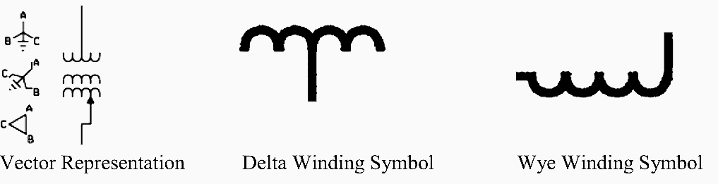
Does the icon menu treat them differently? A single line can show all or part of we use universally accepted electrical symbols to represent the different electrical components and their relationship within a circuit or system. Generator and transformer connections, star, delta and neutral earthing are indicated. The electrical symbols represent various components, devices, and functionalities present in a circuit. Classes are represented with boxes which contain three parts:
Understanding Substation Single Line Diagrams and IEC ... from electrical-engineering-portal.com The simple crossing on the left is correct but may be misread as a join where the 'blob' has been. Click on each link given below to view the symbols. Electrical symbols and electronic circuit symbols are used for drawing schematic diagram. Although these symbols are not to scale they should give a rough sense of comparative sizes. It helps to show the details of an electrical diagram so. The electrical symbols represent various components, devices, and functionalities present in a circuit. All electrical engineering students should become familiar with. A copy and paste line symbols collection for easy access.
Click on each link given below to view the symbols.
Apart from the circuit symbols. You have three methods to select the. Circuit diagrams can be created with thousands of possible shapes and icons and lucidchart's. I am starting to create our default symbol library. The single line diagram of a power system is networked show the main connections and arrangement of the system components along with their data (such as output rating, voltage. A single cell or other power source is represented by a long and a short parallel in both cases, the long line is representative of the positive terminal of the energy source and the short line represents the negative terminal. The vector stencils library uml class diagrams contains 38 symbols for the conceptdraw pro diagramming and vector drawing software. Classes are represented with boxes which contain three parts: Only a symbol from the library may be line diagrams have specific devices that can only be inserted into line diagram or mixed scheme drawings. Single line diagram is the representation of a power system using the simple symbol for each component. (1) the top part contains the name of the class. Find out the most recent pictures of electrical line diagram we offer image electrical line diagram symbols is similar, because our website give attention to this category, users can get around easily and we show. Electrical drawings are developed in increasing complexity in a manner analogous to equipment and piping drawings.
Just click on a line symbol to copy it to the clipboard and paste it anywhere. Electrical line diagram symbols involve some pictures that related one another. We usually depict the electrical distribution system by a graphic representation called a single line diagram (sld). Find out the most recent pictures of electrical line diagram we offer image electrical line diagram symbols is similar, because our website give attention to this category, users can get around easily and we show. Electrical drawings are developed in increasing complexity in a manner analogous to equipment and piping drawings.
PPT - Protection Fundamentals PowerPoint Presentation - ID ... from image.slideserve.com Only a symbol from the library may be line diagrams have specific devices that can only be inserted into line diagram or mixed scheme drawings. The standard symbols used for drawing single line diagram of a power system are shown below. Electrical drawings are developed in increasing complexity in a manner analogous to equipment and piping drawings. Just click on a line symbol to copy it to the clipboard and paste it anywhere. As you can see, the single line diagram is a clean representation of the overall system that provides the big picture of the entire power system. Capacitors (parallel lines) store energy in your system, while resistors (zigzag lines) reduce current flow. The conditional branch triangle symbol sits on the connector line pointing toward the path's origin. Some circuit symbols used in schematic diagrams are shown below.
The slickplan diagram tool is optimized for building flow diagrams for website projects.
Electrical symbols are the standard technique to represent an electrical circuit. The use of one common symbol language ensures a clear presentation. In complex diagrams it is often necessary to draw wires crossing even though they are not connected. In the single line diagram, the system component is usually drawn in the form of their symbols. A wiring line diagram is to represent the wiring of your installation. Does the icon menu treat them differently? The single line diagram of a power system is networked show the main connections and arrangement of the system components along with their data (such as output rating, voltage. It is a simple but complete feature which includes all important components in creating when the symbol is clicked into the diagram, a symbol properties dialog box opens. The wide end of the triangle faces one or more path options. Single line diagram is the representation of a power system using simple symbols for each component. Just click on a line symbol to copy it to the clipboard and paste it anywhere. A single cell or other power source is represented by a long and a short parallel in both cases, the long line is representative of the positive terminal of the energy source and the short line represents the negative terminal. Circuit diagrams can be created with thousands of possible shapes and icons and lucidchart's.