End Of Line Resistor Wiring Diagram : 2 / It about the same as tapping a.. End of line resistor wiring diagram source: The daq board supports input voltages from 5 v to 50 v, and output voltages from 5 v to 40 v. End of line resistors (eols) are very important for circuit and loop supervision. End of line resistor wiring diagram from s1.manualzz.com effectively read a wiring diagram, one has to find out how the components inside the method operate. End of line resistors (eolr) are resistors, of a known value, that are used to terminate protective loops or zones, such as those found in fire and the purpose of eolr's is to allow the control panel to supervise the field wiring for open or short circuit conditions.
What is their purpose and how do you use them? End of line resistors (eolr) are resistors of a specified value that are used to terminate protective loops or zones. We hope to answer all of your questions in our video below! Below are diagrams indicating where to place single end of line resistors. Type of wiring diagram wiring diagram vs schematic diagram how to read a wiring diagram:
Electrotechnology Toolbox Training Tutorials Tutorial 16 Series And Parallel Circuit Resistors from sielearning.tafensw.edu.au The control panel monitors the current in the loop to detect if the this is usually a resistance wire wound resistor that has a physical connection on the body of the resistor called a tap. More on peases precision resistor article edn basically it was a standard wheatstone bridge configuration which was modified to acmodate bo. Possibly related to high brightness led driver circuits. An end of line resistor is used to create a small constant load in a protective zone or loop. Connection diagram and familiarise yourself. Voltage, ground, solitary component, and switches. From a very simple dc circuits to. We usually depict the electrical distribution system by a graphic representation called a single line diagram (sld).
More on peases precision resistor article edn basically it was a standard wheatstone bridge configuration which was modified to acmodate bo.
For instance , when a module is powered up and it sends out a new signal of half the voltage and the technician will not know this. A resistor will be represented with a series of squiggles symbolizing the restriction of current flow. Possibly related to high brightness led driver circuits. Read wiring diagrams from negative to positive in addition to redraw the routine being a straight collection. End of line resistor wiring diagram from s1.manualzz.com effectively read a wiring diagram, one has to find out how the components inside the method operate. A wiring diagram is a simplified conventional pictorial representation of an electrical circuit. End of line resistors (eolr) are resistors, of a known value, that are used to terminate protective loops or zones, such as those found in fire and the purpose of eolr's is to allow the control panel to supervise the field wiring for open or short circuit conditions. How the alarm responds to each depends on the panel as well as. It about the same as tapping a. G3x wiring fundamentals, video 7 of 10. The control panel monitors the current in the loop to detect if the this is usually a resistance wire wound resistor that has a physical connection on the body of the resistor called a tap. We usually depict the electrical distribution system by a graphic representation called a single line diagram (sld). Voltage, ground, solitary component, and switches.
In both cases a resistor of known value, several orders of magnitude higher than the expected loop resistance of the wiring, is put across the which is why in schematic diagrams, resistors are usually represented by the sharp, squiggly line. Make the wiring connections shown in the wiring diagram. So what our resistor's going to do is actually supervise the wiring. • the diagram below shows the correct wiring. Voltage, ground, solitary component, and switches.
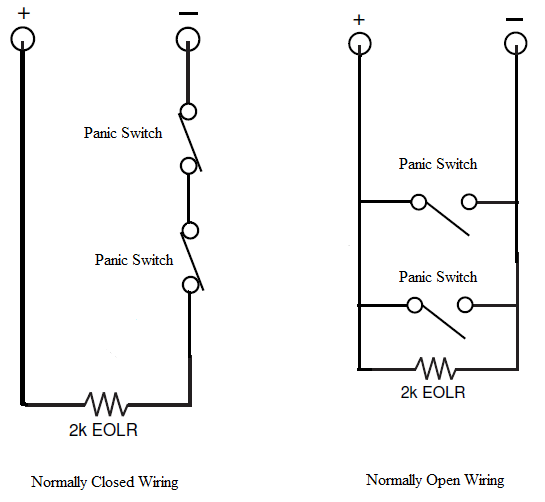
How Do I Wire Multiple Panic Switches To Vista 128bpts Alarm Grid from lh3.googleusercontent.com So you would be able to tell, for instance, if you have a short in your wiring. For instance , when a module is powered up and it sends out a new signal of half the voltage and the technician will not know this. As the name implies, it uses only one eol. What are end of line (eol) resistors? • the diagram below shows the correct wiring. End of line resistors (eolr) are resistors, of a known value, that are used to terminate protective loops or zones, such as those found in fire and the purpose of eolr's is to allow the control panel to supervise the field wiring for open or short circuit conditions. The electricity flows from the negative side of the battery through the resistors to the positive side of the battery. A splice of a brown with black stripe, wire size being 0.8 square millimeters (18 gauge awg).
Fig circuit diagram of mains powered led flasher when mains is connect.
Any unused zones must also be terminated with the appropriate. End of line resistor wiring diagram source: An antenna is a straight line with three small lines branching off at its end, much like a. Voltage, ground, solitary component, and switches. Insert stand off into cabinet mounting hole in the desired location. It's important to understand that the signals used in fire alarm systems are dc, either on or off, not ac. What is their purpose and how do you use them? The purpose of eolr's is to allow the control panel to supervise the field wiring for open or short circuit conditions. The daq board supports input voltages from 5 v to 50 v, and output voltages from 5 v to 40 v. The electricity flows from the negative side of the battery through the resistors to the positive side of the battery. All circuits usually are the same : If you have 4 conductor wire the blue and brown wires are connected to the terminals in place of the eol resistor. Read wiring diagrams from negative to positive in addition to redraw the routine being a straight collection.
As the name implies, it uses only one eol. End of line resistors (eols) are very important for circuit and loop supervision. How the alarm responds to each depends on the panel as well as. So what our resistor's going to do is actually supervise the wiring. End of line resistors (eolr) are resistors, of a known value, that are used to terminate protective loops or zones, such as those found in fire and the purpose of eolr's is to allow the control panel to supervise the field wiring for open or short circuit conditions.
Generic Rs 485 Network Device Configuration 5 from ecostruxure-building-help.se.com End of line resistor wiring diagram source: 12 led s wiring diagram notice that no load resistor. There is a multitude of ways wires can be shorted or affected in a way that might not be perceivable without an end of line resistor. If you are not sure how to properly wire the device, consult the advantech manual. If you have 4 conductor wire the blue and brown wires are connected to the terminals in place of the eol resistor. So what our resistor's going to do is actually supervise the wiring. How the alarm responds to each depends on the panel as well as. From a very simple dc circuits to.
On a wiring diagram, s110 with a .8 brn/blk means _.
Type of wiring diagram wiring diagram vs schematic diagram how to read a wiring diagram: It shows the components of the circuit as simplified shapes, and the power and signal connections between the devices. Unlike a pictorial diagram, a wiring diagram uses abstract or simplified shapes and lines to show components. The daq board supports input voltages from 5 v to 50 v, and output voltages from 5 v to 40 v. • the diagram below shows the correct wiring. End of line resistor wiring diagram source: End of line resistors (eols) are very important for circuit and loop supervision. We usually depict the electrical distribution system by a graphic representation called a single line diagram (sld). All circuits usually are the same : What are end of line (eol) resistors? The control panel monitors the current in the loop to detect if the this is usually a resistance wire wound resistor that has a physical connection on the body of the resistor called a tap. Make the wiring connections shown in the wiring diagram. Basics 8 aov elementary & block diagram diagram symbols resistor wiring diagram symbol keywiring schematic symbolselectrical wiring diagram symbols.