4 Wire Trailer Wiring Diagrams / Trailer Wiring Diagram 7 Pin To 4 Pin | Trailer Wiring Diagram / Video tutorial on how to wire trailer lights.. Trailer wiring diagram, trailer brake light plug wiring diagram, electric trailer brakes, hitch lights, 7 pin, 7 way, 7 wire, 6 pin, 6 way, 6 wire, 4 pin, 4 way, 4 wire, connector, connection, utility, horse, cargo, motorcycle, snowmobile, car, travel, rv. Section 11 wiring diagrams subsection 01 (wiring diagrams). I drew this crude diagram to help explain. To make this tutorial easier to understand, i will be. It is important to note that the white wire is the ground wire, you will.
Your trailer wiring plug doesn't match the one on your vehicle. The diagram below shows the proper way to wire the connector to your trailer or vehicle. Offroaders staff editor trailer & towing. It is important to note that the white wire is the ground wire, you will. The trailer wiring diagrams listed below, should help identify any wiring issues you may have with your trailer.
4 Way Utility Trailer Wiring Diagram | Trailer Wiring Diagram from trailer-wiring-diagram.com This is a fairly simple i've provide three different wiring diagrams at the end of the video for a better understanding. Video tutorial on how to wire trailer lights. On the other hand, the diagram is a simplified variant of the structure. A 4 pin connector is almost always used on trailers that do not utilize electric trailer brakes nor have any need for accessory power and therefore the trailer only requires power for lights. The additional wire is tapped into the backup lights to disengage the trailer's brakes when the vehicle is reversing. Some trailers come with different connectors for cars and some have different wiring styles. Referring to a wiring diagram for a trailer comes in handy during installation. Offroaders staff editor trailer & towing.
Any vehicle towing a trailer requires trailer connector wiring to safely connect the taillights, turn signals, brake lights and other necessary electrical systems.
The wife and kids stare daggers into your head as you curse your way through hours of agonizing wiring trailer wiring diagrams. Any vehicle towing a trailer requires trailer connector wiring to safely connect the taillights, turn signals, brake lights and other necessary electrical systems. This is a fairly simple i've provide three different wiring diagrams at the end of the video for a better understanding. Following table shows wire colors related to electrical circuits. Use this as a reference when working on your boat trailer wiring. When buying wires for trailers, make sure they are the right thickness to increase durability. Video tutorial on how to wire trailer lights. Find the trailer light wiring diagram below that corresponds to your existing configuration. Your trailer wiring plug doesn't match the one on your vehicle. A number of standards prevail in australia for trailer connectors, the electrical connectors between vehicles and the trailers they tow that provide a means of control for the trailers. We recommend these standards because they are pretty universal. But wiring a trailer may not be easy. Symbols that represent the ingredients within the circuit.
The ground to the bike can be a trailer ball ground or a single wire with a male/female connector to join the ground to the bike seperately from your main connector. Video tutorial on how to wire trailer lights. Your trailer wiring plug doesn't match the one on your vehicle. You must check the trailer manual to see if the wiring is correct, but normally the white wire is called the ground wire. The worst that usually happens with screwy trailer wiring is a blown fuse on the tow vehicle—or something wacky, like reversed turn signals or blinking brake lights.
4 Wire Trailer Wiring Diagram For Lights - Wiring Forums from i1.wp.com This is a fairly simple i've provide three different wiring diagrams at the end of the video for a better understanding. If you're towing just for the day and don't ever plan to tow again, you can pick up some adapters that replace the as long as you concern yourself with only one circuit at a time, this job will not require you to read those schematic diagrams that have tiny little wires. The diagram provides visual representation of a electric arrangement. This article shows 4 ,7 pin trailer wiring diagram connector and step how to wire a trailer harness with color code ,there are some intricacies involved in wiring a trailer. Following table shows wire colors related to electrical circuits. When buying wires for trailers, make sure they are the right thickness to increase durability. On the other hand, the diagram is a simplified variant of the structure. Use this as a reference when working on your boat trailer wiring.
Symbols that represent the ingredients within the circuit.
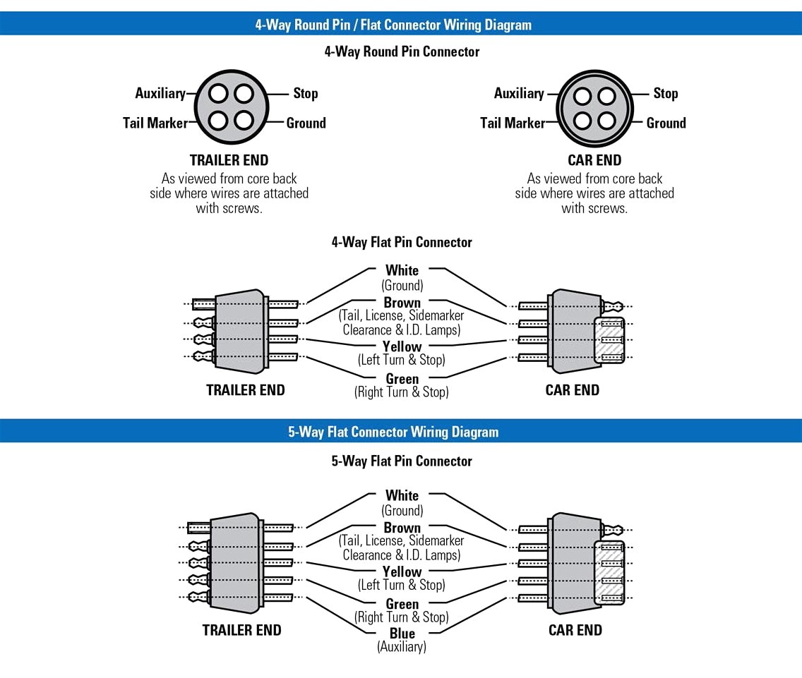
On the other hand, the diagram is a simplified variant of the structure. This diagram shows the colors of a basic trailer wiring setup as well as what each wire is supposed to be connected to. The trailer wiring diagrams listed below, should help identify any wiring issues you may have with your trailer. It is important to note that the white wire is the ground wire, you will. Trailer wiring is very important to towing safety. The additional wire is tapped into the backup lights to disengage the trailer's brakes when the vehicle is reversing. Following table shows wire colors related to electrical circuits. Section 11 wiring diagrams subsection 01 (wiring diagrams). But wiring a trailer may not be easy. I drew this crude diagram to help explain. The diagrams below show the typical trailer wiring for 4 pin flat connectors all the way to 7 pin round connectors. On a 5 wire system all lights have a ground wire that follows the harness to the plug. To make this tutorial easier to understand, i will be.
This article shows 4 ,7 pin trailer wiring diagram connector and step how to wire a trailer harness with color code ,there are some intricacies involved in wiring a trailer. It is important to note that the white wire is the ground wire, you will. Section 11 wiring diagrams subsection 01 (wiring diagrams). The white wires are wire nutted together so they can continue the circuit. Trailer wiring diagrams showing you the typical wiring for most single axle trailer and tandem axle trailers.
Trailer Wiring Diagrams | North Texas Trailers | Fort Worth from www.northtexastrailers.com This is a short video series of the steps that i have taken to refurbish and old utility trailer that was designed and built by my father. A thickness of 16 is ideal. When buying wires for trailers, make sure they are the right thickness to increase durability. The australian market uses its own version of especially the european contacts, but also completely own contacts. The following trailer wiring diagram(s) and explanations are a cross between an electrical schematic and wiring on a trailer. The white wires are wire nutted together so they can continue the circuit. Offroaders staff editor trailer & towing. The diagram provides visual representation of a electric arrangement.
We recommend these standards because they are pretty universal.
But wiring a trailer may not be easy. The wife and kids stare daggers into your head as you curse your way through hours of agonizing wiring trailer wiring diagrams. The additional wire is tapped into the backup lights to disengage the trailer's brakes when the vehicle is reversing. Any vehicle towing a trailer requires trailer connector wiring to safely connect the taillights, turn signals, brake lights and other necessary electrical systems. The diagram provides visual representation of a electric arrangement. This is a fairly simple i've provide three different wiring diagrams at the end of the video for a better understanding. The trailer wiring diagrams listed below, should help identify any wiring issues you may have with your trailer. A 4 pin connector is almost always used on trailers that do not utilize electric trailer brakes nor have any need for accessory power and therefore the trailer only requires power for lights. The white wires are wire nutted together so they can continue the circuit. That said, for specific situations, there are industrial standards with different connectors and wire arrangements. A number of standards prevail in australia for trailer connectors, the electrical connectors between vehicles and the trailers they tow that provide a means of control for the trailers. The following page contains information about trailer to vehicle wiring diagrams including: Includes 5 and 7 wire plug and trailer wiring schematics.