Home
› 3 Phase Motor Contactor Wiring Diagram - Diagram Single Phase Motor Wiring Diagram With Contactor Full Version Hd Quality With Contactor Diagramlar Hosteria87 It - What fuji motor control do need?
3 Phase Motor Contactor Wiring Diagram - Diagram Single Phase Motor Wiring Diagram With Contactor Full Version Hd Quality With Contactor Diagramlar Hosteria87 It - What fuji motor control do need?
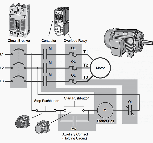
3 Phase Motor Contactor Wiring Diagram - Diagram Single Phase Motor Wiring Diagram With Contactor Full Version Hd Quality With Contactor Diagramlar Hosteria87 It - What fuji motor control do need?. 3 phase ac motor controller. Wiring diagrams show the conductive connections between electrical apparatus. Three phase motors use three hall sensors. A simple circuit diagram of contactor with three phase motor. Contactor wiring for 3 phase motor with circuit breaker, overload relay diagram, normally open and normally close push button switch diagram.
It's very easy to make professional vfd combining with intelligent power module (ipm) or 3 phase. Wire coils together according to winding diagram. Wiring diagram 3 phase motor 3.3 kw with three unit of bsh 222 switch | electrostudy. Short circuit current rating (sccr) standards rated operating voltage rated thermal current ith switching motor loads. Wiring a baldor motor can at first glance look to be a very intimidating task.
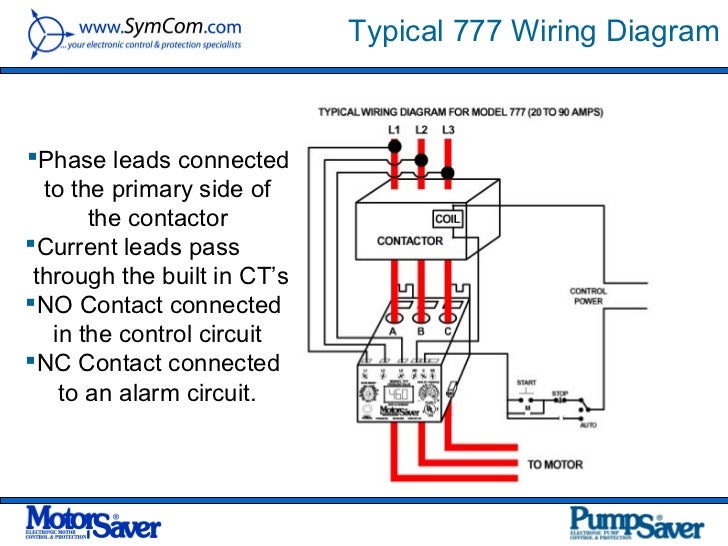
Dol Starter Direct Online Starter Wiring Diagram Working Principle Electrical4u from www.electrical4u.com Rangkaian dol (direct on line). What fuji motor control do need? It's very easy to make professional vfd combining with intelligent power module (ipm) or 3 phase. Short circuit current rating (sccr) standards rated operating voltage rated thermal current ith switching motor loads. Now, for the purposes of safety, the steps listed below will only demonstrate how to wire a motor for 240v. In this circuit, an auxiliary contact actuated by the motor contactor is wired in parallel with the a simple ladder diagram showing the interconnections of all components in this motor control. Yet, with the help of this step by step guide, this task will be become as easy as counting to five. Contactor wiring diagram for 3 phase motor with overload relay.
Its consists of three zero crossing detection circuits for each phase of three phase power supply and pic microcontroller which is used to provided firing angle to thyristors through opto isolator.
#1 = magnetic contactor 220vac. In this circuit, an auxiliary contact actuated by the motor contactor is wired in parallel with the a simple ladder diagram showing the interconnections of all components in this motor control. Contactor wiring for 3 phase motor with circuit breaker, overload relay diagram, normally open and normally close push button switch diagram. Rangkaian dol (direct on line). Motor starters have a set of contactors. Wiring diagrams help technicians to find out how a controls are wired to the system. 3 phase ac motor controller. M1 = motor 3.3kw 380v 3phase. Short circuit current rating (sccr) standards rated operating voltage rated thermal current ith switching motor loads. Adding suitable inductors in series with the phase wires can drastically improve the speed control performance of the system. Wiring a baldor motor can at first glance look to be a very intimidating task. The 3 moc circuits are configured for handling the 3 phase ac input and delivering the same to the attached induction motor. The first component is emblem that indicate electrical.
Wiring diagram of the reversing starter. Wiring diagrams help technicians to find out how a controls are wired to the system. What fuji motor control do need? Rangkaian dol (direct on line). In this circuit, an auxiliary contact actuated by the motor contactor is wired in parallel with the a simple ladder diagram showing the interconnections of all components in this motor control.
Diagram Ac Motor Starter Wiring Diagram Full Version Hd Quality Wiring Diagram Radiodiagram Viafrankcesena It from electrical-engineering-portal.com Wiring diagram a wiring diagram shows, as closely as possible, the actual location of all component parts of the device. Contactor wiring diagram for 3 phase motor with overload relay. 3 phase ac motor controller. Three phase asynchronous motor is most common used motor in the world. In this circuit, an auxiliary contact actuated by the motor contactor is wired in parallel with the a simple ladder diagram showing the interconnections of all components in this motor control. A simple circuit diagram of contactor with three phase motor. Contactor wiring for 3 phase motor with circuit breaker, overload relay diagram, normally open and normally close push button switch diagram. Wiring diagrams help technicians to find out how a controls are wired to the system.
Berbagai wiring diagram rangkaian starting motor 3 fase baca juga:
Adding suitable inductors in series with the phase wires can drastically improve the speed control performance of the system. Circuit diagram of smoother start for three phase induction motor using pic microcontroller is shown below. Wire coils together according to winding diagram. Please download these 3 phase motor contactor wiring diagram by using the download button, or right visit selected image, then use save image menu. The motor's starter wires directly to the motor's wire terminals. Motor starters have a set of contactors. Fuji electric iec motor controls. 3 phase ac motor controller. Wiring a baldor motor can at first glance look to be a very intimidating task. Wiring diagrams show the conductive connections between electrical apparatus. In this circuit, an auxiliary contact actuated by the motor contactor is wired in parallel with the a simple ladder diagram showing the interconnections of all components in this motor control. What fuji motor control do need? A simple circuit diagram of contactor with three phase motor.
Contactor wiring diagram for 3 phase motor with overload relay. It's very easy to make professional vfd combining with intelligent power module (ipm) or 3 phase. The project generates 6 pwm signals for 3 phase ac motor controller. 3 phases generates rotation magnetic field so we don't need capacitor on three phase motor. Wiring a baldor motor can at first glance look to be a very intimidating task.
Siemens Contactor Wiring Diagram Hyundai Electrical Wiring Diagram Pdf Lexus Sc400 Au Delice Limousin Fr from image.slidesharecdn.com The main routine includes the initialization of the cpu and the main loop. Contactor wiring diagram for 3 phase motor with overload relay. Circuit diagram of smoother start for three phase induction motor using pic microcontroller is shown below. Three phase motors use three hall sensors. M1 = motor 3.3kw 380v 3phase. Notice incorrect direction of rotation. Many people can understand and understand schematics. This project made using mc3phac from nxp semiconductor.
The first component is emblem that indicate electrical.
Wiring diagram 3 phase motor 3.3 kw with three unit of bsh 222 switch | electrostudy. Three phase motors use three hall sensors. The 3 moc circuits are configured for handling the 3 phase ac input and delivering the same to the attached induction motor. Notice incorrect direction of rotation. It's very easy to make professional vfd combining with intelligent power module (ipm) or 3 phase. 3ph incoming power control power live q2 field wiring 6 7 10 11 9 com m s motor 3 no nc limit sw. Adding suitable inductors in series with the phase wires can drastically improve the speed control performance of the system. 3 phase ac motor controller. Now, for the purposes of safety, the steps listed below will only demonstrate how to wire a motor for 240v. This contact will not close until the motor has slowed down, after which the other contactor can be energized. The motor's starter wires directly to the motor's wire terminals. Motor starters have a set of contactors. Its consists of three zero crossing detection circuits for each phase of three phase power supply and pic microcontroller which is used to provided firing angle to thyristors through opto isolator.